Futlink
We use cookies to improve your experience and analyse site traffic. By continuing to use our site, you agree to our use of cookies. Read our Privacy Policy.
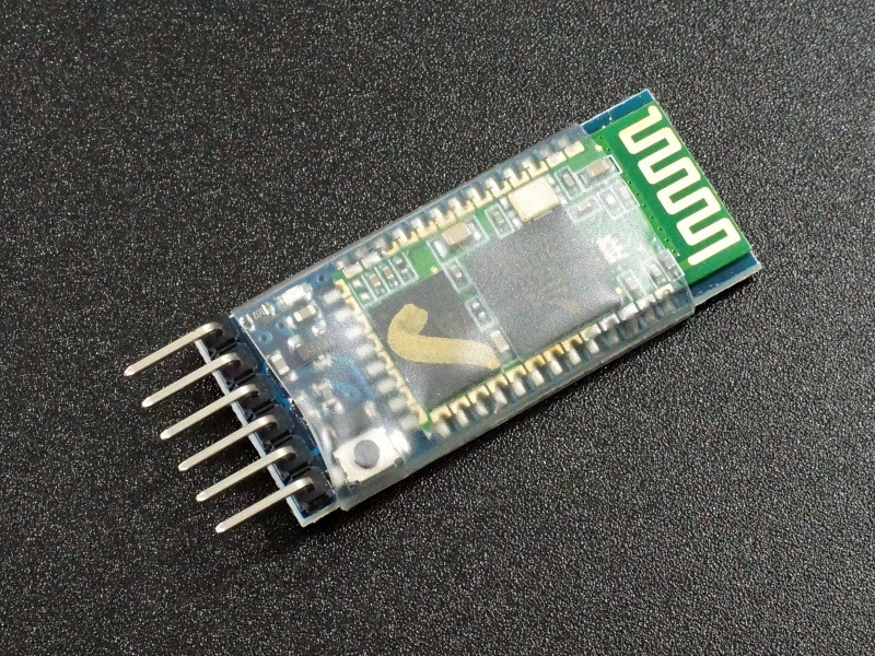
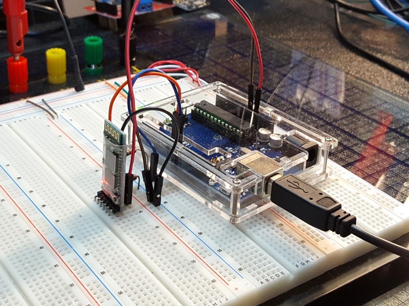
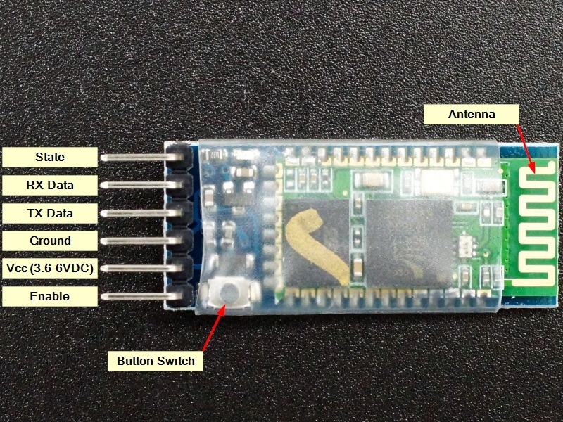
The HC-05 (ZS-040) is a serial to Bluetooth bridge module that allows for wireless communications between two microcontrollers or between a microcontroller and an Android phone, laptop or desktop PC with Bluetooth capability. The HC-05 (ZS-040) can act as both a slave and master device.
PACKAGE INCLUDES:
HC-05 Bluetooth Module with ZS-040 baseboard
KEY FEATURES OF HC-05 BLUETOOTH WITH ZS-040 BASEBOARD MODULE:
Bluetooth V2.0 Operation
ZS-040 Baseboard
Operates in Master or Slave mode
3.6-6V Power
If you are familiar with serial communications with the Arduino or other MCU, using Bluetooth to establish a wireless link is very similar. Bluetooth is designed for short range wireless point-to-point communications. The maximum range is typically around 30 feet and may be less depending on obstructions.
Power
The module operates at 3.3V internally, but the module contains a 3.3V regulator, so the module must be fed with 3.6 – 6V on its Vcc pin. Because the module is 3.3V, the TX line of the uC that goes to the RX pin on the module should have a level shifter installed to drop the logic level down to 3.3V levels as demonstrated in our example below.
Communication Mode
The module defaults to communication mode where it is ready to pair with another Bluetooth device and later when it has been paired. The serial communications in this mode defaults to 9600 baud, but can be changed if desired.
AT Mode
The module can also be put into AT mode of operation where it responds to low level commands.
To enter AT mode, press the button on the module while it is being powered up and then release the button. The LED will flash slowly to indicate it is in AT mode. AT mode allows you to send low level AT commands to the device. Note that the module is in a limited AT mode and some AT commands will not work unless the button is depressed while the command is given.
If the AT mode of operation will be how the module will always be used, the module can be placed into full AT mode by connecting the EN pin to 3.3V. This is the same thing as constantly pressing the button.
When in AT mode, the serial communications default to 38400 baud rate but it can be changed if desired.
LED Indicator
There is an LED on the module that is quite useful to understanding what the module is up to.
When the module is first powered up, it comes up in Bluetooth pairing mode. The LED on the board flashes rapidly at about 2Hz to indicate it is in pairing mode. If the module is paired with a device, the LED flash changes to 2 quick flashes followed by a pause and then repeats.
If the module is instead put into AT mode, the LED will blink at a slow steady rate.
Board Connections:
1 x 6 Header
STATE – The State pin is LOW when unpaired and HIGH when it is paired.
RXD – Receive Data connects to TX on MCU. Use a level shifter if using a 5V MCU
TXD – Transmit Data connects to RX on MCU
GND – Ground
VCC – Power in. Must be between 3.6-6V
EN – Enable AT mode. This pin can be tied to 3.3V if the module will always be used in AT mode
₦5,800
Similar products you may be interested in