Futlink
We use cookies to improve your experience and analyse site traffic. By continuing to use our site, you agree to our use of cookies. Read our Privacy Policy.
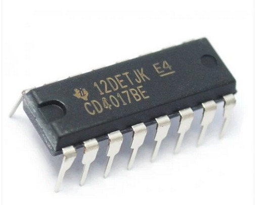
The CD4017 is a 5-stage decade counter/driver that is commonly used in sequential logic applications. It is part of the CMOS 4000 series and features high noise immunity and low power consumption. The IC is capable of counting from 0 to 9 and provides 10 decoded outputs, making it suitable for a variety of applications such as LED chasers, frequency dividers, and event counters. Key Features:
5-stage decade counter with 10 decoded outputs
High-speed operation
Synchronous and asynchronous clear
High noise immunity
Low power consumption
Wide supply voltage range
Direct drive for LEDs
Technical Specifications:
Operating Voltage: 3V to 15V
Maximum Clock Frequency: 5 MHz (at Vcc = 10V)
Output Drive Capability: 10 LSTTL loads
Power Consumption: 0.25 mW (typical)
Propagation Delay Time: 70 ns (at Vcc = 10V)
Package Types: 16-pin PDIP, SOIC, TSSOP
Operating Temperature Range: -55°C to +125°C
Pin Configuration:
Q0 - Output 0
Q1 - Output 1
Q2 - Output 2
Q3 - Output 3
Q4 - Output 4
Q5 - Output 5
Q6 - Output 6
Q7 - Output 7
Q8 - Output 8
Q9 - Output 9
Clock Inhibit - Inhibits the clock input if HIGH
Clock - Clock input
Carry Out - Used to cascade additional counters
Ground (GND) - Connect to system ground
Reset - Resets the count to zero when HIGH
Vcc - Supply voltage
Applications:
LED chasers and sequencers
Frequency dividers
Event counters
Display drivers
Digital clocks
Automated testing systems
Electronic games
Usage:
Connection:
Connect Vcc to the supply voltage (3V to 15V) and GND to ground.
Connect the clock input to the desired clock signal.
Use the reset pin to reset the counter to zero when needed.
Utilize the decoded outputs (Q0-Q9) for driving LEDs, relays, or other loads.
Cascading:
Use the carry-out pin to cascade multiple CD4017 ICs for higher counting ranges.
Control:
Use the clock inhibit pin to pause the counting operation when required.
Implement control logic using the decoded outputs for complex sequential operations.
Caution:
Ensure the supply voltage does not exceed the maximum rated voltage to avoid damage.
Handle the IC carefully to prevent damage from electrostatic discharge (ESD).
Avoid short-circuiting the output pins to prevent excessive current draw.
Datasheet: For detailed technical specifications, refer to the CD4017 Datasheet. The CD4017 is a 5-stage decade counter/driver that is commonly used in sequential logic applications. It is part of the CMOS 4000 series and features high noise immunity and low power consumption. The IC is capable of counting from 0 to 9 and provides 10 decoded outputs, making it suitable for a variety of applications such as LED chasers, frequency dividers, and event counters. Key Features:
5-stage decade counter with 10 decoded outputs
High-speed operation
Synchronous and asynchronous clear
High noise immunity
Low power consumption
Wide supply voltage range
Direct drive for LEDs
Technical Specifications:
Operating Voltage: 3V to 15V
Maximum Clock Frequency: 5 MHz (at Vcc = 10V)
Output Drive Capability: 10 LSTTL loads
Power Consumption: 0.25 mW (typical)
Propagation Delay Time: 70 ns (at Vcc = 10V)
Package Types: 16-pin PDIP, SOIC, TSSOP
Operating Temperature Range: -55°C to +125°C
Pin Configuration:
Q0 - Output 0
Q1 - Output 1
Q2 - Output 2
Q3 - Output 3
Q4 - Output 4
Q5 - Output 5
Q6 - Output 6
Q7 - Output 7
Q8 - Output 8
Q9 - Output 9
Clock Inhibit - Inhibits the clock input if HIGH
Clock - Clock input
Carry Out - Used to cascade additional counters
Ground (GND) - Connect to system ground
Reset - Resets the count to zero when HIGH
Vcc - Supply voltage
Applications:
LED chasers and sequencers
Frequency dividers
Event counters
Display drivers
Digital clocks
Automated testing systems
Electronic games
Usage:
Connection:
Connect Vcc to the supply voltage (3V to 15V) and GND to ground.
Connect the clock input to the desired clock signal.
Use the reset pin to reset the counter to zero when needed.
Utilize the decoded outputs (Q0-Q9) for driving LEDs, relays, or other loads.
Cascading:
Use the carry-out pin to cascade multiple CD4017 ICs for higher counting ranges.
Control:
Use the clock inhibit pin to pause the counting operation when required.
Implement control logic using the decoded outputs for complex sequential operations.
Caution:
Ensure the supply voltage does not exceed the maximum rated voltage to avoid damage.
Handle the IC carefully to prevent damage from electrostatic discharge (ESD).
Avoid short-circuiting the output pins to prevent excessive current draw.
Datasheet: For detailed technical specifications, refer to the CD4017 Datasheet. The CD4017 is a 5-stage decade counter/driver that is commonly used in sequential logic applications. It is part of the CMOS 4000 series and features high noise immunity and low power consumption. The IC is capable of counting from 0 to 9 and provides 10 decoded outputs, making it suitable for a variety of applications such as LED chasers, frequency dividers, and event counters. Key Features:
5-stage decade counter with 10 decoded outputs
High-speed operation
Synchronous and asynchronous clear
High noise immunity
Low power consumption
Wide supply voltage range
Direct drive for LEDs
Technical Specifications:
Operating Voltage: 3V to 15V
Maximum Clock Frequency: 5 MHz (at Vcc = 10V)
Output Drive Capability: 10 LSTTL loads
Power Consumption: 0.25 mW (typical)
Propagation Delay Time: 70 ns (at Vcc = 10V)
Package Types: 16-pin PDIP, SOIC, TSSOP
Operating Temperature Range: -55°C to +125°C
Pin Configuration:
Q0 - Output 0
Q1 - Output 1
Q2 - Output 2
Q3 - Output 3
Q4 - Output 4
Q5 - Output 5
Q6 - Output 6
Q7 - Output 7
Q8 - Output 8
Q9 - Output 9
Clock Inhibit - Inhibits the clock input if HIGH
Clock - Clock input
Carry Out - Used to cascade additional counters
Ground (GND) - Connect to system ground
Reset - Resets the count to zero when HIGH
Vcc - Supply voltage
Applications:
LED chasers and sequencers
Frequency dividers
Event counters
Display drivers
Digital clocks
Automated testing systems
Electronic games
Usage:
Connection:
Connect Vcc to the supply voltage (3V to 15V) and GND to ground.
Connect the clock input to the desired clock signal.
Use the reset pin to reset the counter to zero when needed.
Utilize the decoded outputs (Q0-Q9) for driving LEDs, relays, or other loads.
Cascading:
Use the carry-out pin to cascade multiple CD4017 ICs for higher counting ranges.
Control:
Use the clock inhibit pin to pause the counting operation when required.
Implement control logic using the decoded outputs for complex sequential operations.
Caution:
Ensure the supply voltage does not exceed the maximum rated voltage to avoid damage.
Handle the IC carefully to prevent damage from electrostatic discharge (ESD).
Avoid short-circuiting the output pins to prevent excessive current draw.
Datasheet: For detailed technical specifications, refer to the CD4017 Datasheet.
₦300
Similar products you may be interested in